Choosing the best Laser Cladding Powder is not simply a matter of selecting the hardest alloy. The right choice depends on the substrate, service environment, heat input, and repair objective. A powder that performs well on a steel shaft may crack on cast iron. That difference matters.
Practical selection begins with evidence. Check the powder’s chemical composition, particle size distribution, flowability, and oxygen content. These details affect feeding stability, layer density, and bonding quality. For example, irregular particles may interrupt powder flow through a narrow nozzle. Excessive dilution can also reduce the intended surface performance. Experienced engineers compare supplier data with actual trial results, not marketing claims alone. Small test coupons can reveal cracking, porosity, unmelted particles, or excessive distortion before production begins.
Service conditions deserve equal attention. Consider abrasion, corrosion, impact, temperature, and contact pressure. Nickel-based powders may suit corrosive conditions, while cobalt- or iron-based options may offer different wear and cost advantages. However, no alloy is universally best. That assumption needs correction. A harder coating can become brittle, and a cheaper powder can increase rework costs. Reliable decisions combine technical datasheets, recognized testing methods, equipment compatibility, and advice from qualified materials specialists. Keep records of laser power, scanning speed, powder feed rate, and preheating temperature. Those settings influence results as much as the powder itself. The final selection should be verified through controlled trials and inspection. Good choices are measured, not guessed.
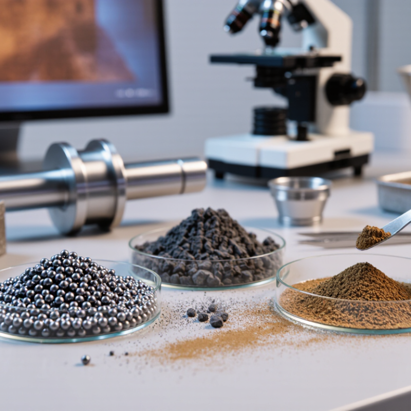
Laser cladding powder is a fine metallic or ceramic-based material fed into a laser-created melt pool. The laser melts the powder and a thin layer of the substrate together. After cooling, this layer can improve wear resistance, corrosion resistance, or surface hardness.
Powder choice matters because chemistry controls the final layer’s performance. Particle size affects feeding stability and melting behavior. Spherical particles usually flow more consistently than irregular particles. Moisture, oxidation, and contamination can create pores, cracks, or weak bonding. In practical workshop trials, even a small change in powder size can alter the track shape. That detail is easy to miss.
Tips: Match the powder to the substrate, service temperature, and expected wear. Check the supplier’s particle-size range, chemical analysis, storage guidance, and safety data. Test a small batch before full production. Record laser power, feed rate, and layer thickness. Repeat the test when conditions change.
Do not select powder by hardness alone. A very hard layer may crack on a softer or thermally sensitive base material. Toughness, dilution, thermal expansion, and compatibility deserve equal attention. The best choice often comes from controlled trials, cross-section inspection, and hardness mapping. Some assumptions will fail. That is useful evidence, not wasted work.
How to Choose the Best Laser Cladding Powder?
Matching powder composition with the base material is the core of reliable laser cladding. Start by identifying the substrate’s chemistry, hardness, thermal conductivity, and service temperature. Steel, cast iron, nickel alloys, and aluminum each respond differently to heat and dilution. A powder that works well on carbon steel may crack on a high-carbon tool steel.
Check compatibility at the fusion boundary. The powder should form a stable metallurgical bond without creating excessive brittle phases. For steel substrates, iron-based powders often control cost and dilution effectively. Nickel-based powders can improve corrosion resistance and tolerate broader chemical variation. Cobalt-based compositions may suit severe wear, but their hardness can increase machining difficulty. Carbide additions require careful control. Too much carbide may produce cracking during cooling.
Small tests matter.
Measure dilution, porosity, hardness, and crack formation on representative coupons. A cross-section can reveal problems hidden by a smooth surface. Keep the laser power, travel speed, powder feed rate, and layer thickness recorded during each trial. I have found that a perfect composition on paper can still fail because of poor preheating or uneven powder delivery. This is where judgment becomes necessary. The hardest powder is not always the best choice. Consider the actual failure mode, repair thickness, finishing method, and expected thermal cycling before approving the final blend.
How to Choose the Best Laser Cladding Powder?
How to Select Powder Properties for the Cladding Process
Choosing laser cladding powder begins with the damaged component, not the powder catalogue. Identify its base metal, service temperature, load, and exposure to wear, corrosion, or impact. Then match the deposited alloy’s chemistry and thermal expansion to that substrate. Poor compatibility can create cracking, dilution, or weak bonding. For abrasive surfaces, hardness matters, but excessive hardness may reduce toughness. Particle size also controls feeding and melting. Fine particles absorb laser energy quickly, while coarse particles may feed more steadily. Use a narrow, documented size range suited to the nozzle and powder feeder.
In production trials, I check spherical morphology, low satellite content, flowability, and apparent density. These properties influence powder delivery and layer consistency. Chemical cleanliness deserves equal attention. Oxides, moisture, and unwanted inclusions can destabilize the melt pool. Ask for measured chemistry, particle-size data, and batch traceability. Do not select powder from hardness data alone. A powder can meet a target hardness yet perform poorly under thermal cycling. Small test coupons reveal more than a polished datasheet. Still, test results can mislead when laser settings differ. That limitation is easy to overlook.
Tips: Compare powders under identical laser power, speed, spot size, and shielding gas. Record deposition efficiency, porosity, cracking, and surface finish. Keep samples from each batch. If feeding becomes erratic, inspect moisture, particle shape, and feeder calibration. Review the decision with a qualified materials engineer.
Particle size is one of the most important powder properties in laser cladding. The chart shows typical particle-size bands used for powder-fed laser cladding, expressed as approximate D10–D90 ranges.
Fine powders can improve feeding accuracy but may increase dust, oxidation, and instability in the powder stream. Standard powder sizes around 45–106 µm are commonly selected for general-purpose coaxial delivery. Coarser powders can provide higher deposition rates, but they require sufficient laser energy and carrier-gas flow. In practice, also verify spherical morphology, low satellite content, consistent flowability, controlled oxygen content, and compatibility with the selected alloy and nozzle.
How to Compare Powder Quality, Cost, and Availability
Choosing laser cladding powder requires more than comparing prices per kilogram. Powder quality affects deposition efficiency, surface finish, and repair reliability. Review the chemical composition, particle size distribution, flowability, and powder morphology. A certificate should show batch results, not only general specifications. Ask for oxygen and moisture data when oxidation could affect the process.
Availability matters. A powder may perform well during testing but create delays if replenishment takes eight weeks. Check current inventory, minimum order quantities, production capacity, and shipping conditions. Keep enough material for repeat trials and future maintenance. Do not guess.
Cost should include waste, sieving, drying, machine time, and post-processing. A cheaper powder can produce more overspray or require additional finishing. Compare the cost per successful deposited part, rather than the cost per kilogram. Small trial coupons can reveal inconsistent feeding, poor bonding, or unexpected hardness before a full production run.
In practical evaluations, I would compare at least two batches under identical laser settings. Record powder consumption, deposition rate, dilution, hardness, and visible defects. This creates evidence instead of relying on attractive data sheets. I have learned that supplier responsiveness also has value. Still, personal experience can be incomplete, so independent testing remains important. A reliable choice balances verified performance, predictable supply, and realistic total cost.
How to Choose the Best Laser Cladding Powder?
How to Validate Powder Performance in the Intended Application
Powder selection should begin with the service environment, not a product catalogue. Define the substrate, working temperature, load, wear mode, and chemical exposure. Then match the powder’s chemistry and particle size to the cladding process. A powder may offer high hardness, yet crack under thermal cycling. That contradiction matters.
Request a certificate of analysis, but verify it independently. Check particle-size distribution, morphology, flowability, moisture, and oxygen content. During qualification, produce test coupons using the intended equipment and similar geometry. Record laser power, scanning speed, feed rate, overlap, and shielding conditions. Small parameter changes can alter dilution and porosity. Watch the melt pool closely.
Examine cross-sections through microscopy. Measure hardness from the surface into the heat-affected zone. Test wear, corrosion, or fatigue under application-specific conditions. Inspect fusion boundaries for cracks, unmelted particles, and trapped pores. Repeat the trial with multiple powder lots. One successful coupon proves very little. A perfect laboratory result can still mislead.
Include realistic interruptions, such as brief cooling periods or repositioning. These details often expose weak process stability. Compare performance against the original component, not only against a target number. Keep raw data, failed samples, and operator observations. The failed sample may explain more than the strongest result. Some qualification plans remain incomplete because they test the coating, but not the finished part.
| Validation Dimension | Nickel-Based Alloy Powder | Cobalt-Based Alloy Powder | Iron-Based Alloy Powder | Metal-Matrix Composite Powder | Recommended Validation Method |
|---|---|---|---|---|---|
| Typical Application Objective | Corrosion resistance, high-temperature service, and general wear protection. | High-temperature wear, erosion, cavitation, and metal-to-metal contact. | Cost-effective wear protection, dimensional restoration, and moderate corrosion resistance. | Severe abrasive wear protection where a hard ceramic phase is acceptable. | Define the dominant failure mode first: corrosion, abrasion, erosion, fatigue, thermal cycling, or dimensional loss. |
| Typical Powder Particle Size | 45–106 µm is commonly used for laser cladding with powder feeding. | 45–106 µm is commonly used for stable powder delivery and melting. | 45–106 µm is commonly used; finer fractions may increase feeding sensitivity. | 45–106 µm for the metallic matrix, with reinforcement particles controlled separately. | Measure particle-size distribution by laser diffraction or sieving. Confirm that the selected range matches the nozzle, carrier-gas flow, and deposition rate. |
| Powder Morphology | Spherical or mostly spherical particles generally provide good flowability and consistent feeding. | Spherical morphology is preferred for stable delivery and reduced satellite formation. | Spherical, dense particles are preferred; irregular particles can increase flow variation. | Inspect matrix-particle bonding and reinforcement distribution; segregation is a key risk. | Use optical microscopy and, where necessary, scanning electron microscopy. Check satellites, hollow particles, agglomerates, and contamination. |
| Apparent Density and Flowability | Typical apparent density is approximately 4.0–5.5 g/cm³, depending on composition and morphology. | Typical apparent density is approximately 4.5–5.5 g/cm³. | Typical apparent density is approximately 3.5–5.0 g/cm³. | Varies widely with ceramic content; segregation and poor flow must be specifically evaluated. | Measure apparent density using a recognized powder-metallurgy method such as ASTM B212 or ISO 3923-1, and measure flow time using ASTM B213 or ISO 4490 where applicable. |
| Typical Hardness After Cladding | Approximately 200–500 HV, depending on alloy chemistry and heat treatment. | Approximately 350–650 HV, depending on carbide content and microstructure. | Approximately 200–700 HV, depending on alloy family and dilution. | Approximately 500–1,200 HV or higher, depending on ceramic reinforcement and test location. | Measure hardness on polished cross-sections using ASTM E384 or ISO 6507. Report load, scale, location, and the number of indents. |
| Wear-Resistance Expectation | Good Suitable for sliding wear and corrosive wear when properly matched to the counterface. |
Very Good Often selected for high-temperature sliding, erosion, and severe adhesive wear. |
Moderate to Very Good Strongly dependent on carbide formation and matrix hardness. |
Excellent for Abrasion Hard reinforcement improves cutting and scratching resistance but may reduce toughness. |
Use a representative test such as ASTM G65 dry-sand/rubber-wheel abrasion, ASTM G99 pin-on-disk wear, or an application-specific test. |
| Corrosion-Resistance Expectation | Very Good Commonly selected for aqueous, chemical, and high-temperature corrosion environments. |
Good to Very Good Depends on chromium, tungsten, carbon, and service chemistry. |
Low to Good Alloy selection must reflect chloride, acid, humidity, and temperature exposure. |
Application Dependent Galvanic effects and exposed reinforcement may influence corrosion behavior. |
Use immersion, electrochemical, or cyclic corrosion testing relevant to the service environment. Avoid relying only on nominal alloy composition. |
| Metallurgical Compatibility | Generally compatible with nickel, stainless, and many nickel-based substrates; dilution must still be controlled. | Generally compatible with cobalt- and nickel-based substrates; thermal expansion mismatch should be assessed. | Often compatible with carbon, low-alloy, and stainless steels; excessive dilution can reduce designed properties. | Compatibility depends on matrix chemistry, reinforcement stability, and substrate thermal behavior. | Review phase diagrams and substrate chemistry. Confirm dilution, metallurgical bonding, and crack sensitivity through cross-sectional microscopy. |
| Crack and Porosity Risk | Usually low to moderate, but increases with high hardness, excessive restraint, contamination, or rapid cooling. | Moderate; carbide-rich grades and high hardness can increase crack sensitivity. | Low to high depending on carbon, alloying level, dilution, and cooling rate. | Moderate to high because ceramic particles can act as stress concentrators or promote incomplete fusion. | Use metallographic examination and image analysis. A practical screening target is low visible porosity and no interconnected cracks in representative cross-sections. |
| Thermal-Cycling Suitability | Good Often suitable for elevated-temperature cycling when thermal expansion is compatible. |
Good Suitable for hot wear, subject to crack-control procedures. |
Moderate Validate carefully when the substrate and coating have different thermal expansion behavior. |
Application Specific High hardness may be offset by reduced strain tolerance. |
Cycle coated specimens between the actual minimum and maximum service temperatures, then inspect hardness, cracks, delamination, and mass loss. |
| Coating Adhesion / Bond Quality | Typically forms a metallurgical bond when adequate melting and low porosity are achieved. | Typically forms a metallurgical bond, but dilution and crack control are important. | Typically forms a metallurgical bond with steel substrates under suitable heat input. | Bond quality depends on complete matrix melting and adequate wetting around reinforcement particles. | Use cross-sectional macrographs, shear or tensile adhesion testing where practical, and inspection for lack of fusion at the interface. |
| Powder Cleanliness and Moisture | Low contamination and dry storage are required to reduce porosity and unstable feeding. | Dry, clean powder is essential because oxides and moisture can impair wetting and increase defects. | Oxide, oil, and moisture contamination can cause porosity and inconsistent powder delivery. | Moisture control is especially important because fine ceramic additions may agglomerate. | Check supplier documentation, storage history, loss on drying, oxygen or nitrogen content when relevant, and visible contamination. |
| Process-Parameter Sensitivity | Moderate; laser power, travel speed, powder feed rate, and overlap affect dilution and solidification. | Moderate to high because high-alloy and carbide-containing grades can have a narrow processing window. | Moderate; excessive heat input may increase dilution and reduce surface hardness. | High; excessive energy can dissolve reinforcement, while insufficient energy can cause lack of fusion. | Build a parameter matrix and record melt-pool stability, bead geometry, dilution, porosity, hardness, and deposition efficiency. |
| Minimum Acceptance Evidence Before Production | Particle-size report, flowability data, cross-section, hardness map, wear or corrosion result, and process repeatability. | Particle-size report, morphology inspection, crack assessment, hardness map, and representative hot-wear result. | Particle-size report, dilution measurement, hardness map, bonding inspection, and application-specific wear result. | Particle-size and segregation data, reinforcement distribution, crack/porosity assessment, hardness map, and abrasive-wear result. | Validate using coupons made with the intended substrate, powder lot, laser system, nozzle, shielding gas, and production parameters. |